Networking
- DNS
- Apple Private Relay on pihole
- Blocking External Client DNS Queries
- Pi-Hole
- Redirecting Client DNS Requests
- Configure Conditional Forwarder on PiHole
- Redirect to a different domain - Cloudflared
- Redirect from root to WWW - cloudflared
- Redirect Domain to New Domain
- DNS Scavenging
- Generate SSL Cert using Command Line
- Network Monitoring PRTG
- pFsense
- SSL Certificates
- T568B Pinout
- Unifi
- Migrating to new Controller
- Setting up the UniFi Network Controller using Docker
- Unifi Console Commands
- Unifi Controller as a Windows Service
- Windows
- OpenSSL generate .PFX file
DNS
Apple Private Relay on pihole
if your Apple device has a DNS issue, but the DNS queries are not showing in the pihole logs you should see something along the lines of mask.icloud.com and mask-h2.icloud.com being blocked as Blocked (Special Domain) nxdomain. This appears to be a problem with Apple Private Relay, which can happen even when this is disabled. Below are the steps to resolve the issue.
Open the pihole server and edit /etc/pihole/pihole-FTL.conf in a text editor of your choice
add the line BLOCK_ICLOUD_PR=false
Save the file and reboot the hardware
After reboot Apple device DNS queries should begin to show properly in the pihole, and the PR mask.icloud.com and mask-h2.icloud.com domains should no longer be visible.
Blocking External Client DNS Queries
Blocking External Client DNS Queries
This procedure configures the firewall to block DNS requests from local clients to servers outside the local network. With no other accessible DNS servers, clients are forced to send DNS requests to the DNS Resolver or DNS Forwarder on pfSense® software for resolution.
Note
Blocking is effective but does not gracefully handle the situation. Clients must manually adjust their configuration to use the firewall for DNS. Redirecting DNS requests to the firewall is a more seamless solution. See Redirecting Client DNS Requests for details.
-
Navigate to Firewall > Rules, LAN tab
-
Create the block rule as the first rule in the list:
-
Click
 Add to create a new rule at the top of the list
 -
Fill in the following fields on the rule:
- Action
-
Reject
- Interface
-
LAN
- Protocol
-
TCP/UDP
- Destination
-
Any
- Destination Port Range
-
DNS (53)
- Description
-
Block DNS to Everything Else
-
-
Create the pass rule to allow DNS to the firewall, above the block rule:
-
Click
Add to create a new rule at the top of the list -
Fill in the following fields on the rule:
- Action
-
Pass
- Interface
-
LAN
- Protocol
-
TCP/UDP
- Destination
-
LAN Address
- Destination Port Range
-
DNS (53)
- Description
-
Pass DNS to the Firewall
-
-
Click
 Apply Changes to reload the ruleset
When complete, there will be two rule entries that look like the following picture:

Certain local PCs could be allowed to use other DNS servers by placing a pass rule for them above the block rule.
DNS over TLS
Another concern is that clients could use DNS over TLS to resolve hosts. DNS over TLS sends DNS requests over an encrypted channel on an alternate port, 853.
This traffic can be blocked with a firewall rule for port 853 using the same procedure used for 53. Though if the firewall will not be providing DNS over TLS service to clients, do not add the pass rule.
DNS over HTTPS
Similar to DNS over TLS, clients may also use DNS over HTTPS (DoH). This is harder to block as it uses port 443. Blocking port 443 on common public DNS servers may help (e.g. 1.1.1.1, 8.8.8.8).
Some browsers automatically attempt to use DNS over HTTPS because they believe it to be more secure and better for privacy, though that is not always the case. Each browser may have its own methods of disabling this feature. Firefox uses a “canary” domain use-application-dns.net by default. If Firefox cannot resolve this name, Firefox disables DNS over HTTPS.
To prevent Firefox from using DNS over HTTPS, add the following to the DNS Resolver custom options:
server:
local-zone: "use-application-dns.net" always_nxdomain
Pi-Hole
Pi-Hole is a DNS server that has built in ability to block queries. It does this by returning 0.0.0.0 for queries on the block list.
| List of Commands |
|
Change password: sudo pihole -a -p Pi-Hole v6 updated command to sudo pihole setpassword
Update: pihole -up |
Redirecting Client DNS Requests
Redirecting Client DNS Requests
Before you begin: Network level DNS must be set to use the pFsense firewall or DNS queries will fail. Attempting to redirect all DNS queries to your own DNS server, only to try and then send them off to Google or Cloudflared will fail.
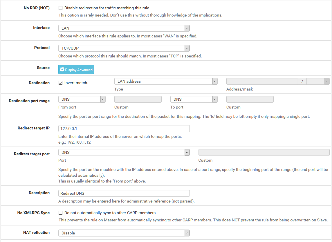
To restrict client DNS to only the DNS Resolver or Forwarder on pfSense® software, use a port forward to capture all client DNS requests.
Note
Either The DNS Resolver or DNS Forwarder must be active and it must bind to and answer queries on Localhost, or All interfaces.
See also
The following example uses the LAN interface but the same technique will work with any local interface.
-
Navigate to Firewall > NAT, Port Forward tab
-
Click
Add to create a new rule -
Fill in the following fields on the port forward rule:
- Interface
-
LAN
- Protocol
-
TCP/UDP
- Destination
-
Invert Match checked, LAN Address
- Destination Port Range
-
DNS (53)
- Redirect Target IP
-
127.0.0.1 - Redirect Target Port
-
DNS (53)
- Description
-
Redirect DNS - NAT Reflection
-
Disable
When complete, the port forward must appear as follows:
Note
If DNS requests to other DNS servers are blocked, such as by following Blocking External Client DNS Queries, ensure the rule to pass DNS to 127.0.0.1 is above any rule that blocks DNS.
With this port forward in place, DNS requests from local clients to any external IP address will result in the query being answered by the firewall itself. Access to other DNS servers on port 53 is impossible.
Tip
This can be adapted to allow access to only a specific set of DNS servers by changing the Destination network from “LAN Address” to an alias containing the allowed DNS servers. The Invert match box should remain checked.
Warning
Clients using DNS over TLS or DNS over HTTPS could circumvent this protection. Redirecting or blocking port 853 may help with DNS over TLS, depending on the clients.
See Blocking External Client DNS Queries for additional advice.
Configure Conditional Forwarder on PiHole
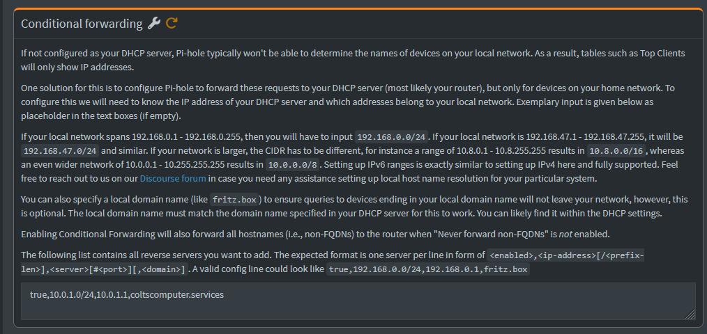
Enter one entry per line like the above
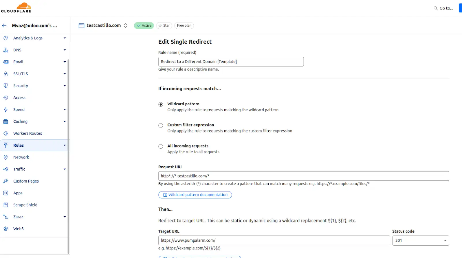
Redirect to a different domain - Cloudflared
https://drive.google.com/file/d/1-uxqWlPEd4vYTOfqIfMYyf_fkyS-vM8D/view?usp=drive_link
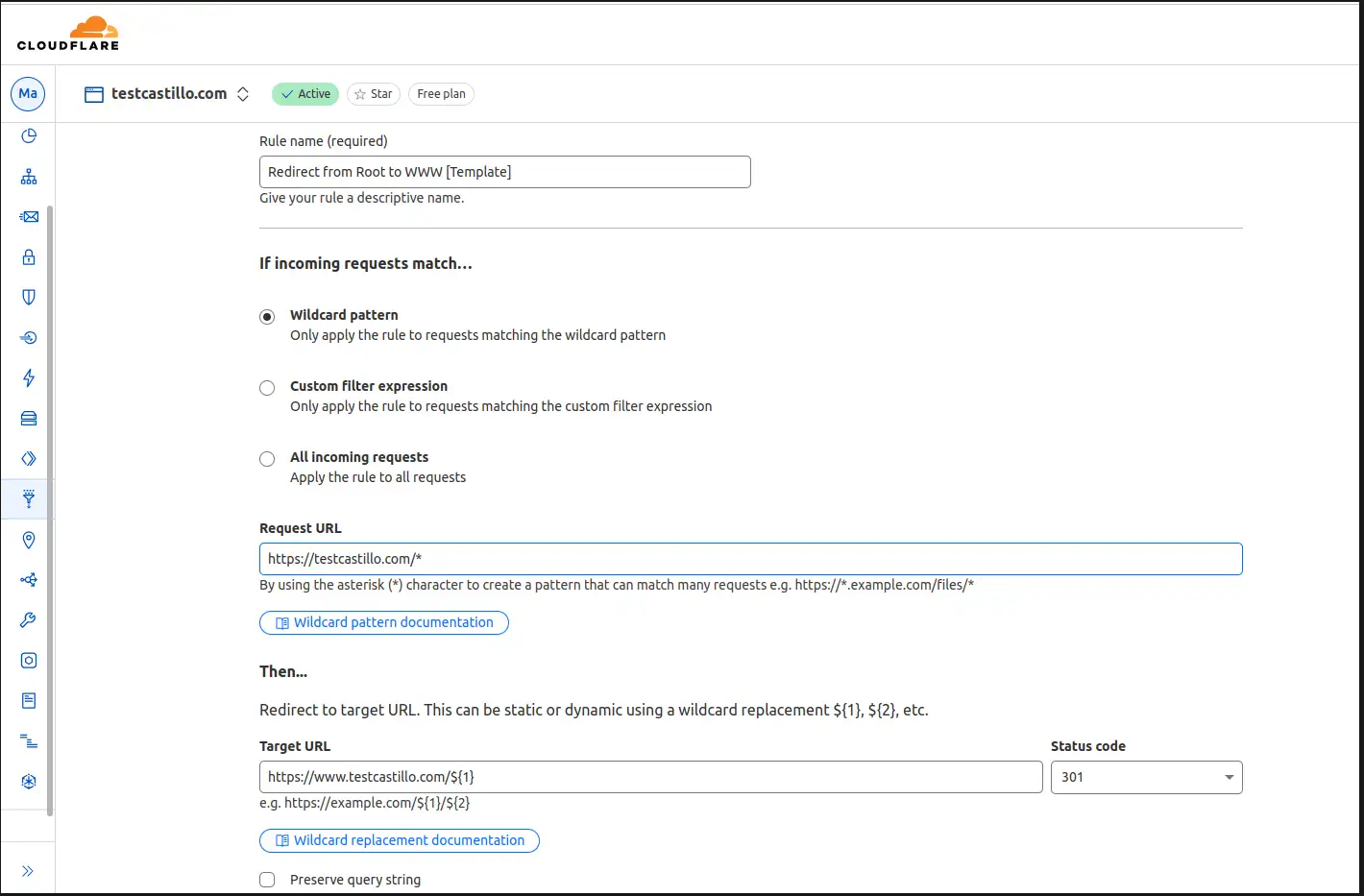
Redirect from root to WWW - cloudflared
https://drive.google.com/file/d/1igk01QjlggVZXxe2pbHMNy_MtNCZoxkC/view?usp=drive_link

Redirect Domain to New Domain
This config should allow you to redirect source.example.com to destination.example.com using cloudflared and Odoo as examples
First setup HTTP 301 redirect rules from the source to the destination domain.

Next configure the DNS records
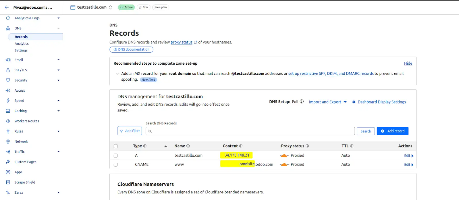
This should redirect www.source.example.com and source.example.com to www.destination.example.com.
#Cloudflared #Odoo #DNS #Redirect
DNS Scavenging
DNS Scavenging is a great answer to a problem that has been nagging everyone since RFC 2136 came out way back in 1997. Despite many clever methods of ensuring that clients and DHCP servers that perform dynamic updates clean up after themselves sometimes DNS can get messy. Remember that old test server that you built two years ago that caught fire before it could be used? Probably not. DNS still remembers it though. There are two big issues with DNS scavenging that seem to come up a lot:
"I'm hitting this 'scavenge now' button like a snare drum and nothing is happening. Why?"
or
"I woke up this morning, my DNS zones are nearly empty and Active Directory is sitting in a corner rocking back and forth crying. What happened?"
This post should help us figure out when the first issue will happen and completely avoid the second. We'll go through how scavenging is setup then I'll give you my best practices.
Scavenging setup
Scavenging will help you clean up old unused records in DNS. Since "clean up" really means "delete stuff" a good understanding of what you are doing and a healthy respect for "delete stuff" will keep you out of the hot grease. Because deletion is involved there are quite a few safety valves built into scavenging that take a long time to pop. When enabling scavenging patience is required. It will work just fine, but not today!
Note: For purposes of this discussion we are going to concentrate on the most common Windows DNS scenario: Windows Server 2003 DNS servers hosting AD integrated zones.
Scavenging is set in three places on a Windows Server:
-
On the individual resource record to be scavenged.
-
On a zone to be scavenged.
-
At one or more servers performing scavenging.
It must be set in all three places or nothing happens.
Scavenging settings on a Resource Record
To see the scavenging setting on a record hit View | Advanced in the DNS MMC then bring up properties on a record.

Scavenging gets set on a resource record in one of three ways. The first is by someone coming in here, checking the "Delete this record when it becomes stale" checkbox and hitting apply. When you hit apply the time of day will be rounded down to the nearest hour and applied as the timestamp on the record. Static records have a timestamp of 0 indicating do not scavenge.
The second is when a record gets created by a client machine registering using dynamic DNS. Windows clients will attempt to dynamically update DNS every 24 hours. All DDNS records get set to scavenge. When a record is first created by a client that has no existing record it is considered an "Update" and the timestamp is set. If the client has an existing host record and changes the IP of the host record this is also considered an "Update" and the timestamp is set. If the client has an existing host record with the same IP address then this is considered a "Refresh" and the timestamp may or may not get changed depending on zone settings. More on this later.
The third way to set scavenging on records is by using DNScmd.exe with the /ageallrecords switch. Let's pause here for a few moments to consider a few important words: All, Records, Delete, Stuff. If you actually run this command against a zone it will truly set scavenging and a timestamp on all records in the zone including static records that you never want to be scavenged. Because of the time it takes scavenging to do it's thing people find this command and get tempted to give it a try. Do not. It will delete stuff. Have patience instead.
Once a timestamp is set on a record it will replicate around to all servers that host the zone. There is one caveat to this. If scavenging is not enabled on the zone that hosts the record then it will never scavenge so the timestamp is essentially irrelevant. The timestamp may get updated on the server where the client dynamically registers but it will not replicate around to the other servers in the zone.
Scavenging Settings at the Zone
Before a server will even look at a record to see if it will be scavenged the zone must have scavenging enabled. To access the scavenging settings for a zone right click the zone, select properties then on the general tab hit the "Aging" button. This screen is universal for the zone. If you view it on any DNS server where this zone is replicated it will be the same.

When you first set scavenging on a zone the timestamp seen at the bottom (reload zone if you don't see it) will be set to the current time of day rounded down to the nearest hour plus the Refresh interval. This also gets reset any time the zone is loaded or any time dynamic updates get enabled on the zone.
The "zone can be scavenged after" timestamp is the first of your safety valves. It gives clients time to get their record timestamp updated before the big axe swings. Since new record timestamps are not replicated while zone scavenging is disabled this also gives replication time to get things in order.
Refresh and No-Refresh intervals
The next safety valves are the Refresh and No-refresh intervals. Both of these must elapse before a record can be deleted.
The No-refresh interval is a period of time during which a resource record cannot be refreshed. Recall from earlier that a refresh is a dynamic update where we are not changing the host/IP of a resource record, just touching the timestamp. If a client changes the IP of a host record this is considered an "update" and is exempt from the No-refresh interval. The purpose of a No-refresh interval is simply to reduce replication traffic. A change to a record means a change that must be replicated.
After the (Record Timestamp) + (No-refresh interval) elapses we enter the Refresh interval. The refresh interval is the time when refreshes to the timestamp are allowed. This is the time when good things must happen. The client is allowed to come in and update it's timestamp. This timestamp will be replicated around and the No-refresh interval begins again. If for some reason the client fails to update it's record during the refresh interval it becomes eligible to be scavenged. Will it disappear immediately? Probably not but it is certainly possible.
Note: When setting Refresh and No-Refresh intervals be sure to allow enough time for clients to get several registration attempts during a Refresh interval. Failure to do so could allow a record to become eligible for scavenging simply from a failed refresh attempt.
One last thing before we leave the zone setting behind. If you right click on your server you will see the option to "Set Aging/Scavenging for All Zones...". Selecting this will take you to a screen similar to the one above. What does this do? This sets the default settings that will be used if a new zone is created by this server. Unless you check the subsequent box "Apply these settings to the existing Active Directory-integrated zones" it will not touch existing zones.
Scavenging settings on the Server
So you now have a resource resource record set to scavenge and a zone set to scavenge. All that is left is for somebody to come along, check all the timestamps and delete some stuff. This is done by any server that hosts the AD integrated zone.
Setting scavenging on the server is done by right clicking the server in the MMC, selecting properties, going to the advanced tab and checking the "Enable automatic scavenging of stale records" checkbox.

The Scavenging Period is how often this particular server will attempt to scavenge. When a server scavenges it will log a DNS event 2501 to indicate how many records were scavenged. An event 2502 will be logged if no records were scavenged. Only one server is required to scavenge since the zone data is replicated to all servers hosting the zone.
Tip: You can tell exactly when a server will attempt to scavenge by taking the timestamp on the most recent 2501/2502 event and adding the Scavenging period to it.
Although you can set every server hosting the zone to scavenge I recommend just having one. The logic for this is simple: If the one server fails to scavenge the world won't end. You'll have one place to look for the culprit and one set of logs to check. If on the other hand you have many servers set to scavenge you have many logs to check if scavenging fails. Worse yet, if things start disappearing unexpectedly you don't want to go hopping from server to server looking for 2501 events.
To facilitate strict control over which server is scavenging for a zone you can use DNSCmd.exe to specify exactly which servers may scavenge. For example the following command will make it so that only 192.168.1.1 and 192.168.1.2 DNS servers are allowed to scavenge on the contoso.com zone:
DNSCmd . /ZoneResetScavengeServers contoso.com 192.168.1.1 192.168.1.2
With the server now scavenging, zones enabled for scavenging, and resources records set what actually happens when the server does it's thing?
The scavenging process and final safety valves
When the last 2501/2052 event + the server scavenging period comes around the server is going to make a scavenging attempt. You can also manually initiate an attempt by right clicking the server and selecting "Scavenge Stale Resource Records". Note that manually making an attempt in no way bypasses the safety valves. These are the final safety valves before we "delete stuff":
-
Is scavenging enabled on the zone? Pretty self explanatory.
-
Is dynamic update enabled on the zone? If it's not there is a good chance timestamps will be old enough that mass deletions can occur.
-
Is the scavenging server listed as one of the "Scavenge Servers" for the zone?
-
Are we past the "zone can be scavenged after" timestamp on the zone? This gives the clients and AD replication to get things squared away before we start.
-
Has it been longer than a refresh interval since this zone was last replicated in Active Directory? If scavenging gets enabled on a server that has replication issues this will prevent it from tombstoning a bunch of records that may be perfectly fine on other servers.
If all of the above checks are good then the zone is ready to be scavenged. At this point the scavenging server checks the timestamp on each individual resource record. If the current date/time is greater than the timestamp + No-refresh + Refresh then the record is deleted.
My best practices
Here is how I set scavenging up on a preexisting zone. This procedure is designed for maximum safety. Using default settings this process can take as long as 4-5 weeks (2 weeks Sanity phase, 2-3 weeks for Enable phase)
Setup phase
-
Turn off scavenging on all servers. To confirm scavenging won't inadvertently run use the DNSCmd /ZoneResetScavengeServers to confine scavenging to a single server then ensure this server has scavenging disabled.
-
Turn on scavenging on the zones you wish to scavenge. Set the refresh and No-refresh intervals as desired. If you want things to scavenge more aggressively I would recommend lowering the No-refresh interval at the cost of some replication traffic. Leave the refresh at the default.
-
Add today's date plus the Refresh and No-Refresh intervals. Come back in a few weeks when this time has elapsed. Seriously you can't rush this.
Sanity check phase
Sift through your DNS records looking for any records older than the Refresh + No-Refresh interval. If you see any then something has gone wrong with the dynamic registration process and it must be corrected before proceeding. A thorough check at this point is the most important step in setup
Things to check if you find old records:
-
Does an IPConfig /registerdns work?
-
Who is the owner of the record (see security tab in the record properties)?
-
Was the record statically created by an admin then later enabled for scavenging? If so you may need to delete the record to clear ownership and run an IPConfig /registerdns to get it updated.
-
Is the server replicating OK with AD?
Do not proceed unless you can explain any outdated records. In the next phase they will be deleted.
Enable phase
The final step is to actually enable scavenging. Enable scavenging on the single server you used the /ZoneResetScavengServers command on.
Once enabled create a new test record and enable it for scavenging. Then map out the point in time when this record will disappear. Here is how:
-
Start with the timestamp on the record
-
Add the refresh interval
-
Add the no refresh interval
-
The result will be your "eligible to scavenge" time. The record will not disappear at this time though. It's just eligible.
-
Check your DNS event logs for 2501 and 2502 events to find what hour the DNS server is doing a scavenging run.
-
Take your "eligible to scavenge" time, find the most recent 2501/2502 event and add the server's Scavenging Period (from server properties | advanced tab) to it. This is the point in time when the test record you just created will disappear.
Lets look at an example with the following assumptions:
-
Zone is set to a 3 day Refresh and a 3 day No-Refresh interval
-
Server Scavenging period is set to 3 days
-
Last DNS Event id 2501 or 2502 occurred at 6am on 1/1/2008
-
We have a record with a timestamp of 1/1/2008 at 12:00 noon
Given these assumptions you can rub your temples for a bit and predict that the record will be deleted at approximately 6am on 1/10/2008.

Once scavenging is enabled you can check back periodically to look for the 2501 and 2502 events to see how things are going. You can also come back at the predicted date and time and see if your test record disappeared.
That's it!
Generate SSL Cert using Command Line
Install openssl on Windows:
In cmd.exe: C:\> winget install openssl
Then from its folder go with C:\> openssl req -newkey rsa:2048 -nodes -x509 -keyout server.key -out server.crt
Linux sudo apt install openssl
openssl ecparam -list_curves
openssl ecparam -out ec_key.pem -name secp256r1 -genkey openssl req -new -key ec_key.pem -x509 -nodes -days 365 -out cert.pemNetwork Monitoring PRTG
Integrate PRTG with Active Directory
By default, PRTG uses its own internal user account database to authenticate users. For many PRTG
customers, particularly those with smaller networks, this local authentication meets all their needs.
But for PRTG customers who have more complex environments and infrastructures or who want to reduce the number of authentication mechanisms in their networks, PRTG offers Active Directory (AD) integration as well.
This way, all members of the AD user groups that are mapped to user groups in PRTG during the integration can log in to PRTG with their AD domain credentials afterward.
1. Prepare your Active Directory for PRTG integration
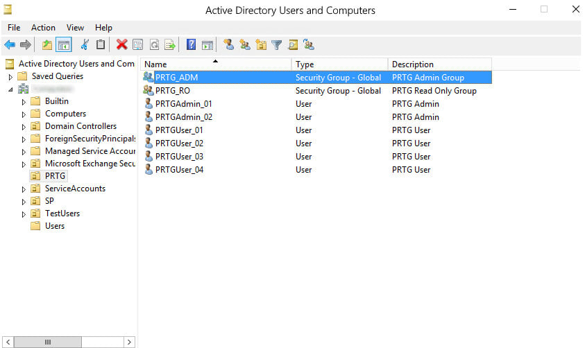
In the AD, make sure that users who require the same access rights for PRTG are in the same AD user group.
In our example, the AD user group PRTG_ADM contains the two administrator user accounts that later have administrative rights in PRTG and that can also manage access rights and cluster setups and change the monitoring configuration of PRTG. The AD user group PRTG_RO contains the four user accounts that later have only read access rights in PRTG.
2. Prepare your PRTG core server system
Make sure that the PRTG core server system is a member of the AD domain with which you want to integrate it. You can check and, if necessary, change this setting via the Windows Control Panel:
3. Add Active Directory domain details to PRTG
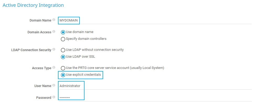
In the next step, you need to provide your local AD domain details in PRTG:
- Open the PRTG web interface and select Setup | System Administration |
Core & Probes from the main menu. - Go to section Active Directory Integration and enter your local AD domain name in the Domain Name field.
- Choose your preferred LDAP Connection Security
- Under Access Type, select Use explicit credentials to define the Windows service account that PRTG uses to authenticate against the AD.
 The service account must have the Read permissions, Read all properties, and List contents permissions for all your AD user groups.
 - Under User Name, enter the service account name that PRTG uses to access the AD.
- Under Password, enter the respective password of the service account.
- Click Save.
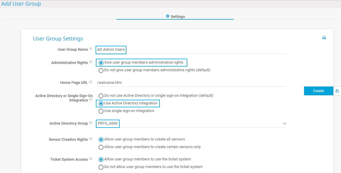
4. Add new user groups in PRTG
- In the PRTG web interface, select Setup | System Administration | User Groups from the main menu.
- Hover over
 and select Add User Group.
 - Provide a meaningful User Group Name.
- Under Administrative Rights, select Give user group members administrative rights.
- Under Active Directory or Single Sign-On Integration, select Use Active Directory integration.
- Under Active Directory Group, select the AD user group whose members later have access to PRTG. For our example, we chose the PRTG_ADM user group. For very large ADs, you see an input field instead of a dropdown list when you add or modify a user group. In this case, you can only enter the AD user group name. PRTG automatically adds the prefix.
Repeat these steps for the PRTG_RO user group to create a second group of users that have only read access rights for PRTG. In this case, leave the default setting under Administrative Rights.
Now, members of the defined AD groups can log in to PRTG with the respective access rights.
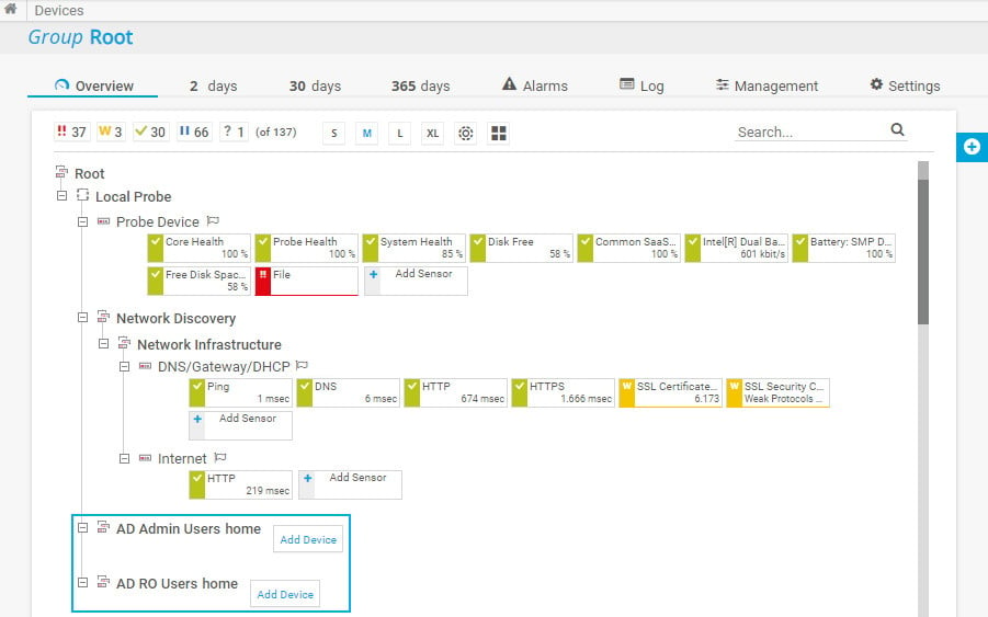
In the device tree, PRTG automatically creates new groups with the name [group_name] home for each of the integrated AD user groups.
Do not forget to set group access rights that apply to device tree objects as well as to libraries, maps, and reports. You can do so in an object’s settings in section Access Rights.
The easiest way is to set group access rights in the settings of the root group.
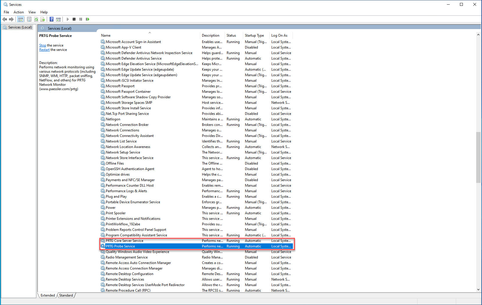
PRTG Server is running but all probes are down
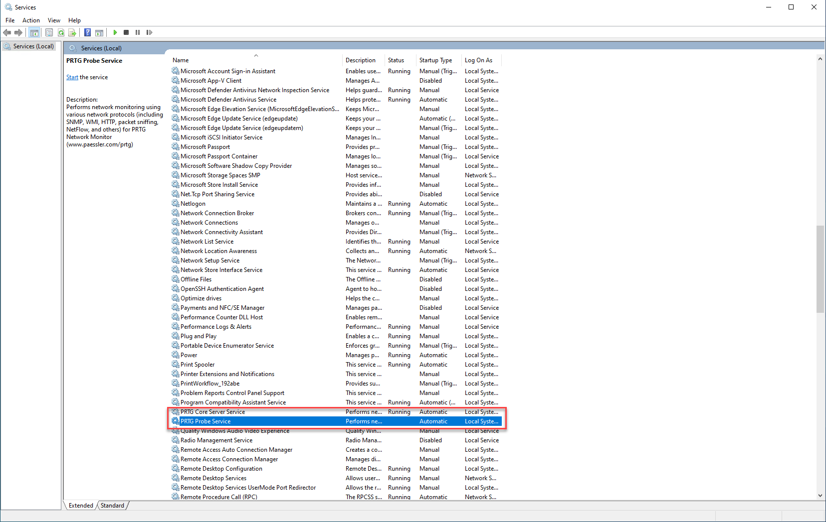
Both highlighted services need to be running
pFsense
Aliases
Aliases
Aliases define a group ports, hosts, or networks. Aliases can be referenced by firewall rules, port forwards, outbound NAT rules, and other places in the firewall. Using aliases results in rulesets that are significantly shorter, self-documenting, and more manageable.
Note
Firewall aliases are collections of entries for use by the firewall. Despite the similar names, this is different than interface IP aliases, which are a means of adding additional IP addresses to a network interface (Virtual IP Addresses).
Aliases are located at Firewall > Aliases. The page is divided into separate tabs for each type of alias: IP, Ports, URLs, and the All tab which shows every alias in one large list. When creating an alias, add it to any tab and it will be sorted to the correct location based on the type chosen.
Nesting Aliases
Most aliases can be nested inside of other aliases to collect many entries into larger groups. For example, one alias can nest an alias containing web servers, an alias containing mail servers, and a servers alias that contains both the web and mail server aliases all together in one larger Servers alias.
To nest, aliases must be either the same or compatible types. For example, a network type alias cannot nest a port alias since they are not the same type of alias. However, host and network aliases can nest each other since they are compatible. URL table aliases can nest other URL table aliases, and URL aliases can nest other URL aliases.
Using Hostnames in Aliases
Host and network type aliases support entries consisting of fully qualified domain name (FQDN) style hostnames (e.g. host.domain.com) in regular or IDN format. The firewall must be able to resolve the hostname as-is using A or AAAA type DNS queries in order for these entries to function. This means that the firewall must have working DNS, and the FQDN must exist in the DNS servers used by the firewall.
Warning
This process only supports forward name resolution of FQDNs using A and AAAA records such as host.domain.com. Aliases do not support pattern matches, wildcard matches (e.g. *.domain.com), or any other style of record comparison.
If the DNS query for a hostname returns multiple IP addresses, all of the IP addresses returned in the result at the time the query is made are added to the alias.
Note
This feature is not useful for allowing or disallowing users to large public web sites such as those served by content delivery network (CDN) providers. Such sites tend to have constantly rotating or random responses to DNS queries so the contents of the alias on the firewall do not necessarily match up with the response a user will receive when they resolve the same site name. It can work for smaller sites that have only a few servers and do not include incomplete sets of addresses in their DNS responses.
A hostname entry in a host or network type alias is periodically resolved and updated by the firewall every few minutes. The default interval is 300 seconds (5 minutes), and can be changed by adjusting the value of Aliases Hostnames Resolve Interval on System > Advanced, Firewall & NAT tab. This is useful for tracking dynamic DNS entries to allow specific users into services from dynamic IP addresses.
Mixing IPv4 and IPv6 Addresses in Aliases
IPv4 and IPv6 addresses can be mixed inside an alias. The firewall will use the appropriate type of addresses when the alias is referenced in a specific rule.
Alias Sizing Concerns
The total size of all tables must fit in roughly half the amount of Firewall Maximum Table Entries, which defaults to 400000. If the maximum number of table entries is not large enough to contain all of the entries, the rules may fail to load. See Firewall Maximum Table Entries for information on changing that value. The aliases must fit in twice in the total area because of the way aliases are loaded and reloaded; The new list is loaded alongside the old list and then the old one is removed.
This value can be increased as much required provided that the firewall contains sufficient RAM to hold the entries. The RAM usage is similar to, but less than, the state table but it is still safe to assume approximately 1K of memory per entry to be conservative.
Alias Settings
When editing an Alias entry, the following settings are available:
- Name
-
A Name for the alias. The name may only consist of the characters
a-z,A-Z,0-9and_. - Description
-
A Description for the alias.
- Type
-
The Type for the alias, which alters the behavior of the alias and tells the firewall which types of entries can be added to the alias.
The following types are available:
- Host
-
Aliases containing single IP addresses or FQDN hostnames
- Network
-
Aliases containing CIDR-masked lists of networks, FQDN hostnames, IP address ranges, or single IP addresses
- Port
-
These aliases contain lists of port numbers or ranges of ports for TCP or UDP.
- URL (IP or Port)
-
The alias is built from the content returned by the specified URL, but is read only a single time. Once added, it becomes a normal network or port type alias.
- URL Table (IP or Port)
-
The alias is built from the content returned by the specified URL but is updated by fetching the list from the URL periodically.
- Entries
-
The lower section of the alias page contains the entries for the alias. The behavior of this section varies based on the selected alias type.
The next sections describe the behavior of each type in more detail.
Host Aliases
Host type aliases contain groups of IP addresses. For Host type aliases, entries are specified by IP address or fully qualified domain name (FQDN).
If an IP address range such as 192.168.1.1-192.168.1.10 or a small subnet such as 192.168.1.16/28 is entered in this field, the firewall will translate it into a list of individual IP addresses when saving the alias.
Figure Example Hosts Alias shows an example of a host type alias used to contain a list of public web servers.
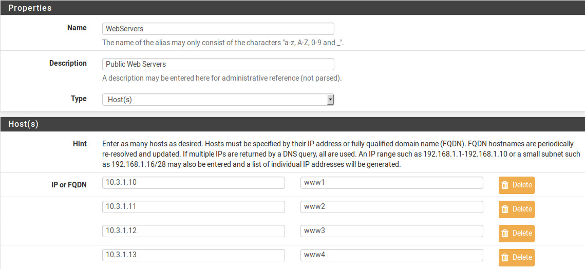
Example Hosts Alias
Other host type aliases can be nested inside this entry. Hostnames may also be used as entries, as explained previously.
Network Aliases
For Network type aliases, entries are specified in CIDR format for subnets or fully qualified domain names (FQDN) for single addresses.
For subnets, select the CIDR mask that pertains to each entry. /32 specifies a single IPv4 host, /128 specifies a single IPv6 host, /24 specifies 255.255.255.0, /64 specifies a normal IPv6 network, etc.
Hostnames (FQDNs) may also be specified, using a /32 mask for IPv4 or /128 for IPv6.
Figure Example Network Alias shows an example of a network alias that is used later in this chapter.
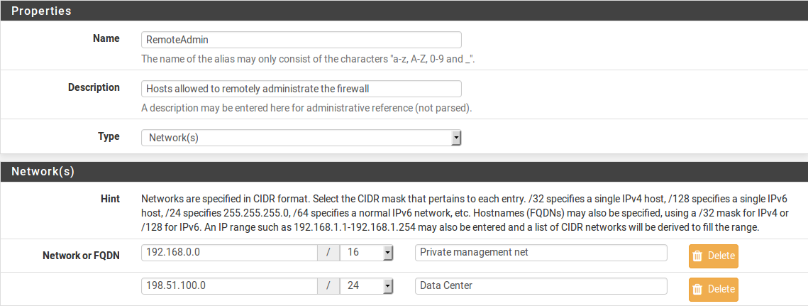
Example Network Alias
Other host or network aliases can be nested inside this entry. Hostnames may also be used as entries, as explained previously.
When an alias entry contains an IPv4 range it is automatically translated by the firewall to an equivalent set of IPv4 CIDR networks that will exactly contain the provided range. As shown in Figure Example IP Range After, the range is expanded when the alias is saved, and the resulting list of IPv4 CIDR networks will match exactly the requested range.

Example IP Range Before
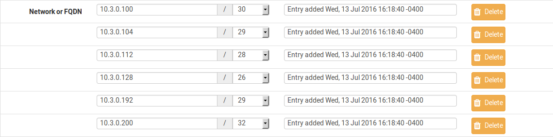
Example IP Range After
Port Aliases
Port type aliases contain groups of ports and port ranges. A single port is an integer from 1-65535. A port range is two ports separated by a colon (:), for example, 1194:1199 and matches the specified ports and any ports in between.
The protocol is not specified in the alias; The firewall rule where the alias is used will define the protocol as TCP, UDP, or both. Figure Example Ports Alias shows an example of a port type alias.
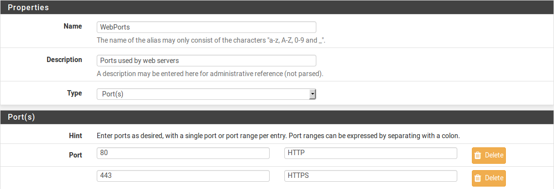
Example Ports Alias
Enter another port-type alias name into the Port field to nest other port-type aliases inside this alias.
URL Aliases
With a URL type alias, each entry contains a URL which returns text content containing a list of entries. Multiple URLs may be entered.
When Save is clicked, up to 3,000 entries from each URL are read from the file and imported into a network type alias.
If URL (IPs) is selected, then the URLs must contain IP address, CIDR masked network entries, or FQDNs, and the firewall creates a network type alias from the contents.
If URL (Ports) is selected, then the URL must contain only port numbers or ranges, and the firewall creates a port type alias from the contents.
For a URL type alias, the contents of the alias are re-fetched every 24 hours from the stored URL by the firewall.
URL Table Aliases
A URL Table alias behaves in a significantly different way than the URL alias. For starters, it does not import the contents of the file into a normal alias. It downloads the contents of the URL into a special location on the firewall and uses the contents for what is called a persist table, also known as a file-based alias. The full contents of the alias are not directly editable in the GUI, but can be viewed in the Tables viewer (See Firewall Table Contents).
For a URL Table alias, the drop-down list after the / controls how many days must pass before the contents of the alias are re-fetched from the stored URL by the firewall. When the time comes, the alias contents will be updated overnight by a script which re-fetches the data.
URL Table aliases can be quite large, containing many thousands of entries. Some customers use them to hold lists of all IP blocks in a given country or region, which can easily surpass 40,000 entries. The pfBlockerNG package uses this type of alias when handling country lists and other similar actions.
If URL Table (IPs) is selected, then the URLs must contain IP address, CIDR masked network entries, or FQDNs, and the firewall creates a network type alias from the contents.
If URL Table (Ports) is selected, then the URL must contain only port numbers or ranges, and the firewall creates a port type alias from the contents.
Configuring Aliases
To add an alias:
-
Navigate to Firewall > Aliases
-
Click
 Add
Add -
Enter settings as described in Alias Settings
-
Enter the type-specific information as needed. Each type has an data field and a description field for each entry.
To add new members to an alias, click Add at the bottom of the list of entries.
To remove members from an alias, click  Delete at the end of the row to remove.
When the alias is complete, click Save to store the alias contents.
Each manually entered alias is limited to 5,000 members, but some browsers have trouble displaying or using the page with more than around 3,000 entries. For large numbers of entries, use a URL Table type alias which is capable of handling larger lists.
Bulk Import Network Aliases
Another method of importing multiple entries into an alias is to use the bulk import feature.
To use the import feature:
-
Navigate to Firewall > Aliases
-
Click
 Import
 -
Fill in the Alias Name and Description
-
Enter the alias contents into the Aliases to import text area, one entry per line.
-
Click Save
Common usage examples for this page include lists of IP addresses, networks, and blacklists. The list may contain IP addresses, CIDR masked networks, IP ranges, or port numbers. The firewall will attempt to determine the target alias type automatically.
The firewall imports items into a normal alias which can be edited later.
Using Aliases
When a letter is typed into an input box which supports aliases, the GUI displays a list of matching aliases. Select the desired alias from the list, or type its name out completely.
Note
Alias autocompletion is not case sensitive but it is restricted by type. For example, a Network or Host type alias will be listed in autocomplete for a Network field, but a Port alias will not; A port alias can be used in a port field, but a Network alias will not be in the list.
Figure Autocompletion of Hosts Alias shows how the WebServers alias, configured as shown in Figure Example Hosts Alias, can be used in the Destination field when adding or editing a firewall rule.
-
Edit the firewall rule
-
Select Address or Alias
-
Then type the first letter of the desired alias: Enter
Wand the alias appears as shown.
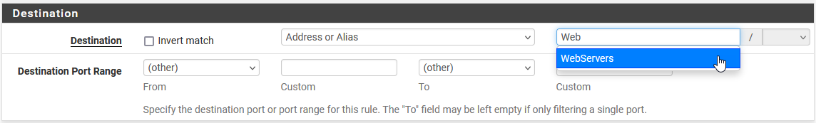
Autocompletion of Hosts Alias
Figure Autocompletion of Ports Alias shows the autocompletion of the ports alias configured as shown in Figure Example Ports Alias. If multiple aliases match the letter entered, all matching aliases of the appropriate type are listed. Click on the desired alias to select it.

Autocompletion of Ports Alias
Figure Example Rule Using Aliases shows the rule created using the WebServers and WebPorts aliases. This rule is on WAN, and allows any source to the IP addresses defined in the WebServers alias when using the ports defined in the WebPorts alias.

Example Rule Using Aliases
Hovering the mouse cursor over an alias on the Firewall > Rules page shows a tooltip displaying the contents of the alias with the descriptions included in the alias. Figure Hovering Shows Hosts Contents shows this for the WebServers alias and Figure Hovering Shows Ports Contents for the ports alias.
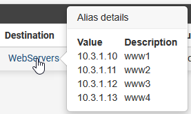
Hovering Shows Hosts Contents
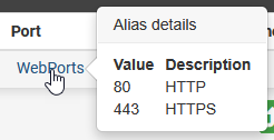
Hovering Shows Ports Contents
Basic Firewall Configuration Example
Basic Firewall Configuration Example
This article is designed to describe how pfSense® software performs rule matching and a basic strict set of rules. The approach described in this document is not the most secure, but will help show how rules are setup.
Rules on the Interface tabs are matched on the incoming interface.
See also
Read the Aliases article as it will make management of rules easier.
Basic lock down of the LAN and DMZ outgoing rules
Outbound LAN
Make sure the Default LAN > any rule is either disabled or removed.
-
Allowing DNS access:
-
If pfSense is the DNS server:
-
Allow TCP/UDP 53 (DNS) from LAN subnet to LAN Address.
-
-
If using Upstream DNS Servers:
-
Allow TCP/UDP 53 (DNS) from LAN subnet to Upstream DNS Servers.
-
-
Otherwise:
-
Allow TCP/UDP 53 (DNS) from LAN subnet to anywhere.
-
-
-
Allowing all users to browse web pages anywhere:
-
Allow TCP 80 (HTTP) from LAN subnet to anywhere.
-
-
Allowing users to browse secure web pages anywhere:
-
Allow TCP 443 (HTTPS) from LAN subnet to anywhere.
-
-
Allowing users to access FTP sites anywhere:
-
Allow TCP 21 (FTP) from LAN subnet to anywhere.
-
-
Allowing users to access SMTP on a mail server somewhere:
-
Allow TCP 25 (SMTP) from LAN subnet to anywhere.
-
-
Allowing users to access POP3 on a mail server somewhere:
-
Allow TCP 110 (POP3) from LAN subnet to anywhere.
-
-
Allowing users to access IMAP on a mail server somewhere:
-
Allow TCP 143 (IMAP) from LAN subnet to anywhere.
-
-
Allowing remote connections to an outside windows server for remote administration:
-
Allow TCP/UDP 3389 (Terminal server) from LAN subnet to IP address of remote server.
-
-
Allowing LAN to access windows shares on the DMZ, via NETBIOS/Microsoft-DS:
-
Allow TCP/UDP 137 from LAN subnet (NETBIOS) to DMZ subnet.
-
Allow TCP/UDP 138 from LAN subnet (NETBIOS) to DMZ subnet.
-
Allow TCP/UDP 139 from LAN subnet (NETBIOS) to DMZ subnet.
-
Allow TCP 445 from LAN subnet (NETBIOS) to DMZ subnet.
-
Outbound DMZ
By default, there are no rules on OPT interfaces.
-
Allowing servers to use Windows update or browse the WAN:
-
Allow TCP 80 from DMZ subnet (HTTP) to anywhere.
-
Allow TCP 443 from DMZ subnet (HTTP) to anywhere.
-
-
Allow users to connect to an external DNS server:
-
Allow TCP/UDP 53 from DMZ subnet (DNS) to IP address of the upstream DNS server(s)
-
-
Allowing servers to use a remote time server:
-
If using an upstream remote time server:
-
Allow UDP 123 from DMZ subnet (NTP) to IP address of remote time server.
-
-
Otherwise:
-
Allow UDP 123 from DMZ subnet (NTP) to any.
-
-
Setup isolating LAN and DMZ, each with unrestricted Internet access
The following setup can be used instead if outbound access is more lenient, but still controlled between local interfaces. This assumes all local networks are privately numbered, and that interfaces have already been configured.
Create an alias, Firewall > Aliases from the main menu, called RFC1918 containing 192.168.0.0/16, 172.16.0.0/12, and 10.0.0.0/8.
LAN Configuration
-
For DNS from the firewall:
-
Allow TCP/UDP from LAN subnet to LAN Address port 53.
-
-
For accessing the GUI:
-
Allow TCP from LAN subnet to LAN address port 443.
-
-
To ping the firewall from the LAN:
-
Allow ICMP from LAN subnet to LAN address.
-
-
If there is any traffic required from LAN to DMZ:
-
Allow any traffic required from LAN to DMZ.
-
-
Do not allow LAN to reach DMZ or other private networks:
-
Reject Any from LAN subnet to RFC1918.
-
-
For internet access:
-
Allow Any from LAN subnet to any.
-
DMZ Configuration
-
For DNS from the firewall:
-
Allow TCP/UDP from DMZ subnet to DMZ Address port 53.
-
-
For accessing the GUI (optional):
-
Allow TCP from DMZ subnet to DMZ address port 443.
-
-
To ping the firewall from the DMZ:
-
Allow ICMP from DMZ subnet to DMZ address.
-
-
If there is any traffic required from DMZ to LAN:
-
Allow any traffic required from DMZ to LAN.
-
-
Do not allow DMZ to reach LAN or other private networks:
-
Reject Any from DMZ subnet to RFC1918.
-
-
For Internet access:
-
Allow Any from DMZ subnet to any.
-
Additional Interfaces
Repeat the above pattern as needed.
Blocking Web Sites
Blocking Web Sites
There are several options for blocking websites with pfSense® software, some of which are described on this article. This is not an exact science, but these solutions typically function well enough for a majority of use cases.
See also
The pfBlockerNG package (pfBlocker-NG Package) offers mechanisms which can be useful in this area, such as DNSBL, geographic IP address blocking, and automation of AS lookups.
Using DNS
If the built in DNS Resolver or Forwarder are active an override can be entered there to resolve the unwanted website to an invalid IP address such as 127.0.0.1.
Warning
Do not use DNS override functionality as the only means of blocking access to sites.
Blocking via DNS requires that local clients utilize the firewall as their only DNS source. See Redirecting Client DNS Requests and Blocking External Client DNS Queries for suggestions on ensuring clients get their DNS responses from the firewall. It will stop non-technical users, but it is easy to circumvent for those with more technical aptitude.
With the DNS Resolver, additional methods are possible via custom options.
This first example will prevent any host under the given zone from being resolved by clients:
server:
local-zone: "movie.edu" static
When the firewall enforces DNS resolution in this way, the firewall must also force clients to resolve DNS using the firewall. Otherwise, clients could bypass the restrictions by using alternate DNS servers. See Redirecting Client DNS Requests for details.
This can be limited in scope using custom views. This example is similar to the above, but only blocks access for 10.6.0.100:
server:
access-control-view: 10.6.0.100/32 blocksites

view:
name: "blocksites"
local-zone: "movie.edu" static
Using Firewall Rules
If a website rarely changes IP addresses, then it can be blocked by an alias. Create an alias containing its IP addresses and then use this alias in firewall rules.
Warning
This is not a feasible solution for sites that return low TTLs and spread the load across many servers and/or datacenters, such as Google and similar large sites. Most small to mid sized websites can be effectively blocked using this method as they rarely change IP addresses.
A hostname can also be inside a network alias. The firewall will resolve the hostname periodically and update the alias as needed. This is more effective than manually looking up the IP addresses, but will still fall short if the site returns DNS records in a way that changes rapidly or randomizes results from a pool of servers on each query, which is common for large sites.
Another option is finding all of the IP subnet allocations for a site. Create an alias with those networks and block traffic to those destinations. This is especially useful with sites such as Facebook that spread large amounts of IP space, but are constrained within a few net blocks. Using regional registry sites such as ARIN can help track down those networks. For example, all of the networks used by Facebook in the region covered by ARIN can be found at http://whois.arin.net/rest/org/THEFA-3.html under “Related Networks”. Companies may have other addresses in different regions, so check other regional sites as well, such as RIPE, APNIC, etc.
As an alternative to looking up the IP blocks manually, locate the BGP Autonomous System (AS) number for the target company by doing a whois lookup on one of their IP addresses. For example, the AS number for Facebook is AS32934 and the following command will locate all of their allocations:
# whois -h whois.radb.net -- '-i origin AS32934' | awk '/^route:/ {print $2;}' | sort | uniq
Copy the results of that command into a new alias and it will cover all of their currently allocated networks. Check the results periodically for updates.
Using a Proxy
In modern environments a client proxy is not effective. HTTPS can sometimes be filtered via peek/splice to inspect SNI and similar aspects of connections, but even that fails with modern security practices like encrypted SNI. Using proxies for these tasks is no longer a recommended practice.
Prevent Bypassing Restrictions
With any of the above methods, there are many ways to get around the defined blocks. The easiest and likely most prevalent is using any number of proxy websites. Finding and blocking all of these individually and keeping the list up to date is impossible. The best way to ensure these sites are not accessible is using an external proxy or content filtering capable of blocking by category.
To further maintain control, use a restrictive egress ruleset and only allow traffic out to specific services and/or hosts. For example, only allow DNS access to the firewall or the DNS servers specifically used for LAN clients (Redirecting Client DNS Requests). Also, if a proxy is in use on the network, make sure to disallow direct access to HTTP and HTTPS through the firewall and only allow traffic to and/or from the proxy server.
SSL Certificates
https://onepagezen.com/free-ssl-certificate-wordpress-google-cloud-click-to-deploy/
https://www.onepagezen.com/letsencrypt-auto-renew-certbot-apache/
T568B Pinout

Unifi
Migrating to new Controller
- Take a backup of the old server
- Restore the backup onto the new server
- on the old server set the override inform host option to point at the new controller
- verify the devices have shown up in the new controller
- shutdown the old controller
Setting up the UniFi Network Controller using Docker
https://pimylifeup.com/unifi-docker/
Once you have Docker installed, our next step is to prepare your system to run the UniFi Network Controller container.
The main thing we need to do here is create a directory to store the UniFi containers Compose file and all of its data.
You can create this directory by running the following command within the terminal.
sudo mkdir -p /opt/stacks/unifiCopyBy utilizing the “-p” option, this command will create any missing directories in the given path.
5. After creating a directory to store our Compose file, we can change to the directory by using the cd command.
cd /opt/stacks/unifiCopyWriting a Compose file for the UniFi Docker Container
6. Our next step is writing the Compose file for the UniFi docker container. This Compose file will instruct Docker what image to download and the environment variables to pass through to it.
You can begin writing this file by typing in the following command.
sudo nano compose.yamlCopy7. Within this file, you will want to type in the following lines.
You must replace “<TIMEZONE>” with a valid TZ Identifier. You can find a list of time zone identifiers from Wikipedia.
For example, we would use “Australia/Hobart” for our time zone.
services:
  unifi:
    user: unifi
    image: ghcr.io/jacobalberty/unifi-docker
    container_name: unifi-controller
    restart: unless-stopped
    ports:
      - "8080:8080"
      - "8443:8443"
      - "3478:3478/udp"
      - "10001:10001/udp"
    environment:
      TZ: "<TIMEZONE>"
    volumes:
      - ./data:/unifiCopy
8. Once you have written the lines above, save and quit by pressing CTRL + X, followed by Y, and then the ENTER key.
Starting the UniFi Docker Container
9. With the Compose file written, all you need to do to bring the UniFi network controller Docker container online is to use the following command.
We use the “-d” option to detach from the current terminal session once the container has started.
docker compose up -dCopyAccessing the UniFi Network Controller Web Interface
10. Now that you have the Docker container for the UniFi network controller running, you will want to access its web interface. You will also need to know the IP address later in this guide.
If you don’t know the local IP address of your machine, you can get it by running the following command.
hostname -ICopyEnsure you set up your device with a static IP address before proceeding further. You do not want your UniFi controller to be assigned a dynamic IP address.
11. Once you know the IP address of your device, go to the following address in your favourite web browser.
Ensure that you replace “<IPADDRESS>” with your IP.
https://<IPADDRESS>:8443Initial Set Up of the UniFi Network Controller
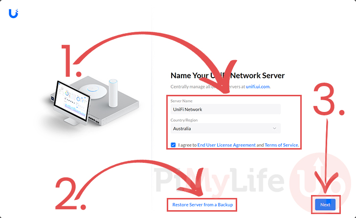
12. When you first access your new Docker-based UniFi Network controller, you must complete some initial set up steps.
If you are setting up this controller as a brand new one, give it a server name, select your country, and accept the terms and conditions (1.).
After filling out your servers details, click the “Next” button (3.) to continue.
However, if you are restoring this from an older UniFi backup, click the “Restore Server from a Backup” link (2.)
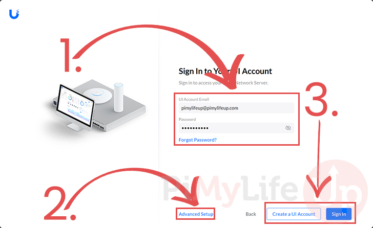
13. If you are setting this controller up from scratch, you will now be asked to sign in to your Ubiquiti account (1.).
After filling out an email and password you can click the “Create a UI Account” button to create a new account, or you can click the “Sign In” button (3.) if you already have an account.
If you prefer not to use a Ubiquiti account on your controller, click the “Advanced Setup” link and follow the prompts (2.).
14. At this point, you should now have access to the UniFi network controller web interface.
However, before you can start adopting your Ubiquiti network devices, there is an option you must enable.
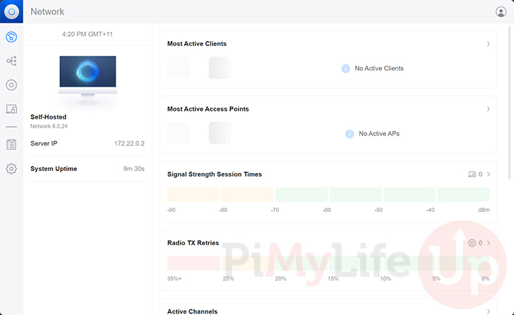
Enabling the Inform Host Option
15. For your Ubiquiti devices to detect your Docker-based UniFi network controller, we must enable the “Inform Host” option.
This option lets us tell the IP address the controller should broadcast to available devices. Currently, it will be using the Dockers internal IP rather than the host IP.
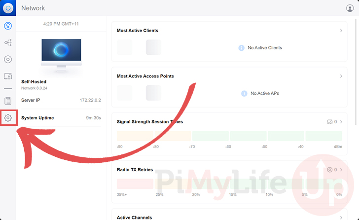
To set this option, you must first switch to the settings page by clicking the cog in the sidebar.
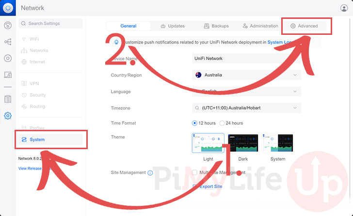
16. Once you are on the settings screen, change to the “System” menu (1.).
After changing to the system settings page, swap to the “Advanced” tab (2.).
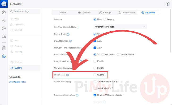
17. On this page, you should find an option labeled “Inform Host“.
Click the checkbox to allow us to begin overriding the host IP.
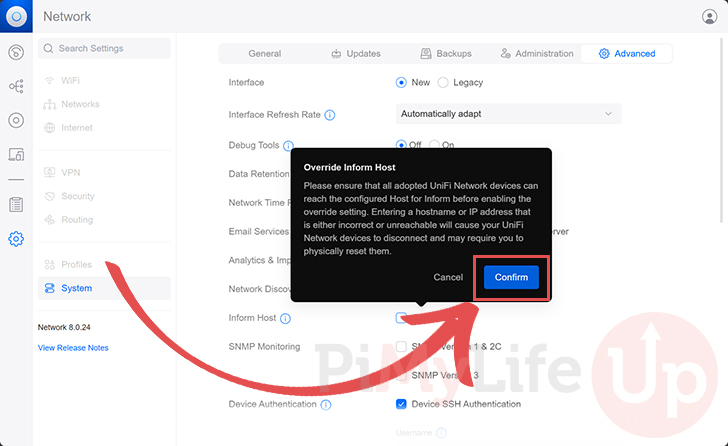
18. Before you can override the inform host value, you will get a warning that misconfiguring this option can cause you to lose access to your devices. You may have to physically reset your Ubiquiti devices if something goes wrong.
You need to ensure that the IP address of your host is correct and reachable. If you are happy to proceed, click the “Confirm” button.
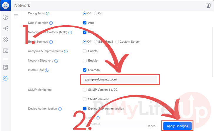
19. A text box will now appear below the “Inform Host” option. Type in the local IP address (1.) of the machine on which you are running the UniFi network controller using Docker.
Once you are happy that you have typed in the correct IP address, click the “Apply Changes” button (2.).
20. Once you have applied your settings, you must restart the UniFi Docker container.
Back in the terminal, you can bring the UniFi container down by using the following command
docker compose downCopy21. Start UniFi back up on your device by running the following command within the terminal.
docker compose up -dCopyUpdating your UniFi Docker Container
One massive advantage of using the UniFi network controller through a Docker container is that updating it is straightforward.
The following steps will walk you through the effortless way of updating to the latest version. You can see what versions are available by visiting the GitHub page for this project.
1. To update the UniFI container, we must change to the directory we created earlier in this guide.
We need to use the Compose file we wrote to pull the latest version of the image.
cd /opt/stacks/unifiCopy2. After swapping to the directory where we wrote the Compose file, you can use the command below to download the latest version of the UniFi container.
docker compose pullCopy3. Finally, if a new version is found, you can get Docker to move over to it using the command below in the terminal.
Docker will detect the new image and restart the container using it.
docker compose up -dUnifi Console Commands
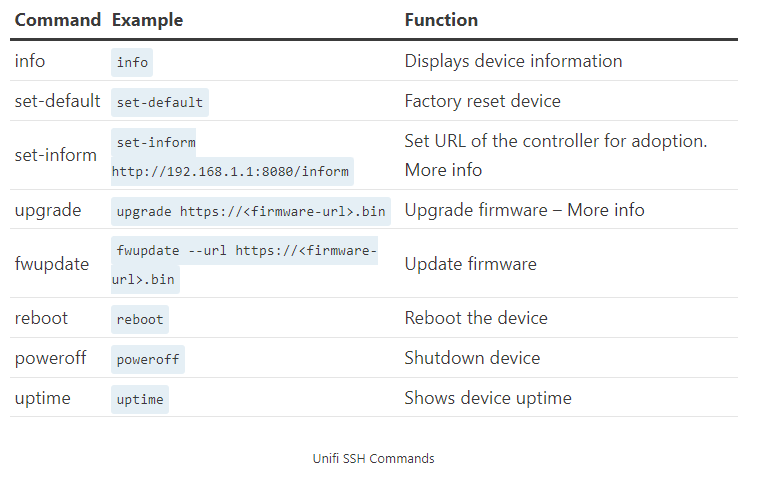
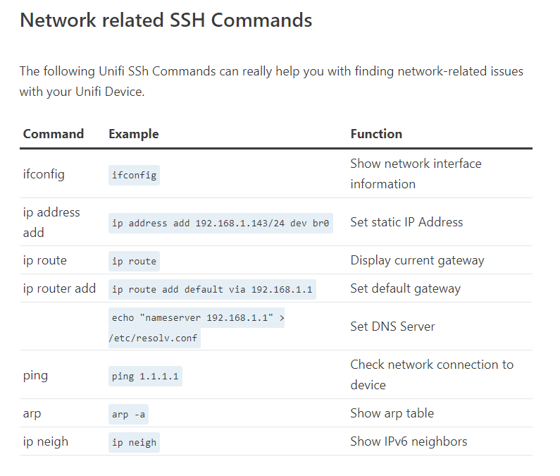
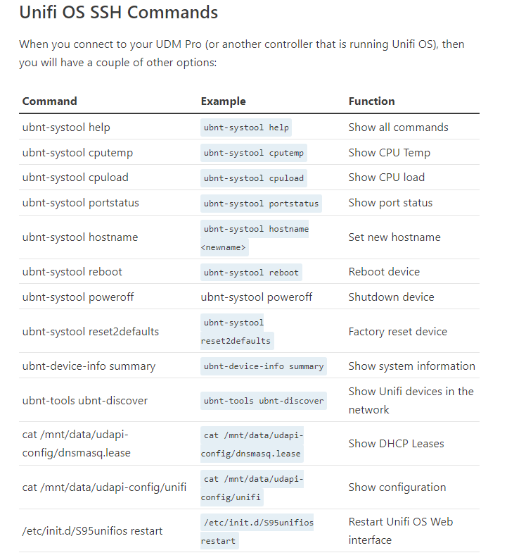
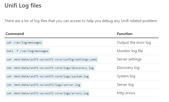
Unifi SSH
Unifi Controller as a Windows Service
How to Set Up the UniFi Network Controller as a Windows Service
1. Close any instances of the UniFi software on the computer. If the UniFi Network Controller was just installed, make sure to open the controller software manually at least once, or let it run at the end of the wizard. Once you see the message UniFi Controller (a.b.c) started, the controller may be closed.
2. Launch the Command Prompt as an Administrator. On Windows 10 this would entail right-clicking and selecting "Run as administrator". Please see Windows documentation to identify the appropriate method for your specific Windows version.
3. Change directory to the location of UniFi in the computer using the following command (exactly as it is here, no need to substitute anything):
cd "%UserProfile%\Ubiquiti UniFi\"
4. Once in the root of the UniFi folder, issue the following command to install the UniFi Network Controller service:
java -jar lib\ace.jar installsvc
5. Once you're at a new command prompt line, after it says “Complete Installation…”, issue the following:
java -jar lib\ace.jar startsvc
6. Close the command prompt window either by entering the exit command, or clicking the X.
7. To access the UniFi Network Controller now open a browser and go to https://localhost:8443. Alternatively, the desired interface IP, or FQDN that is mapped to that host (in place of “localhost”) may be used.
NOTE: We recommend using Oracle Java JRE 8, which can be downloaded in Oracle's website. For the UniFi Cloud Access portal (https://network.unifi.ui.com/) to work properly, only use x64 Java.
How to Upgrade a UniFi Network Controller that is Running as a Windows Service
1. Open the UniFi Network Controller and make a backup.
2. Launch the Command Prompt as an Administrator. On Windows 10 this would entail right-clicking and selecting "Run as administrator". Please see Windows documentation to identify the appropriate method for your specific Windows version.
3. Change directory to the location of UniFi in the computer using the following command (exactly as it is here, no need to substitute anything):
cd "%UserProfile%\Ubiquiti UniFi\"
4. Once in the root of the UniFi folder, issue the following to stop and uninstall the UniFi Network Controller service:
java -jar lib\ace.jar stopsvc
java -jar lib\ace.jar uninstallsvc
5. Once a new command prompt line is presented, that means uninstalling the service was successful. Update the UniFi Network Controller application's version with any of the regular methods. Go to Settings > Maintenance in the Controller to upgrade to the latest public released version, or alternatively download the UniFi Network Controller installation package for Windows from the Downloads page or the Releases section of the Community.
6. Once the software update is successful, close the UniFi Network Controller application before going back to the Command Prompt.
7. In the Command Prompt issue the following to install the UniFi Network Controller service once again:
java -jar lib\ace.jar installsvc
8. Once you're at a new command prompt line, after seeing the "Complete Installation…" message, issue the following:
java -jar lib\ace.jar startsvc
9. Close the Command Prompt window either by entering the exit command, or clicking the X.
10.To access the UniFi Network Controller now open a browser and go to https://localhost:8443. Alternatively, the desired interface IP, or FQDN that is mapped to that host (in place of “localhost”) may be used.
Unifi
Windows
Windows
|
Wireless troubleshooting |
netsh wlan show wlanreport |
|
Shows wifi profiles |
netsh wlan show profiles |
|
Delete wifi profile |
netsh WLAN delete profile name="Profile_Name" |
|
Connect to wifi |
netsh wlan connect ssid=YOUR_WIFI_SSID name=PROFILE_NAME |
|
List network interfaces |
netsh interface show interface |
|
Disable an interface |
netsh interface set interface "Wi-Fi" disable |
|
Purge kerberos tickets - use before gpudate to pull new computer groups |
klist -lh 0 -li 0x3e7 purge |
|
PS continuous ping with timestamps and output to file |
Ping.exe -t wei-01-pc27 | ForEach {“{0} – {1}” -f (Get-Date),$_} | Tee C:\Accent\pingtest.txt |
|
Search ARP table by MAC Addr with Powershell |
Get-NetNeighbor | ? { $_.LinkLayerAddress -eq "88-6F-D4-B8-1D-AD" } |
|
Get link speed and duplex of NIC |
Get-NetAdapter | SELECT name, LinkSpeed, fullduplex | ft -autosize |
|
Get firewall active profile |
Get-NetConnectionProfile |
|
Set firewall active profile |
Set-NetConnectionProfile -InterfaceAlias Ethernet1 -NetworkCategory "Public" |
|
qwinsta /server:<servername> or query session |
Find RdP sessions |
|
rwinsta /server:<servername> <session ID> |
End RDP session |
OpenSSL generate .PFX file
openssl pkcs12 -inkey STAR.example.com_key.txt -in STAR.example.com.crt -export -out example_pfx.pfx
OPENSSL PFX
On Windows server to properly import you may need to specify encryption
openssl pkcs12 -macalg SHA1 -keypbe PBE-SHA1-3DES -certpbe PBE-SHA1-3DES -export -out website.pfx -inkey private.key -in a01f36fe692456.crt -certfile gd_bundle-g2-g1.crt